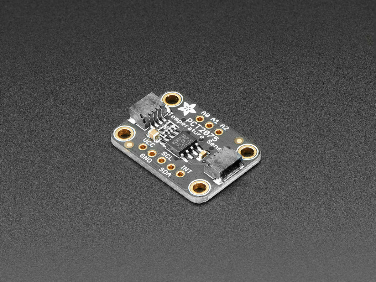
I decided to write a device driver in Rust to expand on my skills. I happened to have a PCT2075 sensor breakout board from Adafruit. Before starting on the driver, I looked on crates.io and didn't see a crate for it. I later found out from the datasheet that this sensor is a pin-for-pin replacement for the LM75 temperature sensor. From this discovery, I found an LM75-rs crate. At first, I thought that I would have to choose another sensor, but reading the datasheet further...perharps not 🙂
It turned out that the PCT2075 used an ADC with 11-bit resolution where the LM75 only had 9-bit resolution. It also contained another configuration register, the idle register (T_idle). This register holds an 8-bit value, however only the lower 5 bits are used with the others being "don't care". The sample rate value held in the T_idle register represents the number of milliseconds between temperature conversions. For example, a value of 0b1_1111 has a decimal value of 31, multiple this by 100 ms increments, and you get a sample rate of 3100 ms, or 3.1 seconds. This is the maximum delay that can be set between temperature sampling operations. The default and also fastest sample rate is 100 ms with a register value of 0b0_0001. Writing a zero to this register will fail over to the default value of 100 ms.
The final difference I found from the datasheet, was the number of addresses the sensor could assume. The lm75only allows for 8 possible addresses coming from the A2, A1, and A0 pins and whether these are logically set to HIGH or LOW. The implication being that these pins must not be disconnected. The pct2075 allows for any of these pins to remain unconnected, or floating. Once the sensor is powered on, it will sample the A0-A2 pins then latch to that address. Since each of those pins can take on 3-states instead of just 2, the sensor can assume up to 27 different addresses. In other words, up to 27 different sensors can be connected to the same I2C bus.
With these differences, I decided it was worth the effort to add support for the pct2075 to the lm75-rs crate. The implementation turned out to be a little tricky. You want to re-use the most code possible from the original crate, but also sneak in all that extra functionality. There is a really nice solution to this problem, zero-sized types I made use of PhantomData which allows for markers to be applied to the I2C structure to signal the sensor's capabilities but not actually create another field. The PhantomData acts like it stores a value of type <T> even though it doesn't. As a zero-sized type (ZST), it means exactly that, it has zero impact on the run time and does not take up any memory. In the code below, the <IC> represents the chip, or integrated circuit, that the struct implements.
/// LM75 device driver.
#[derive(Debug, Default)]
pub struct Lm75<I2C, IC> {
    /// The concrete I²C device implementation.
    i2c: I2C,
    /// The I²C device address.
    address: u8,
    /// Configuration register status.
    config: Config,
    /// Device Marker
    _ic: PhantomData<IC>,
}
A ResolutionTrait is implemented on the IC struct that we are using to represent which type of sensor we are using. This trait allows use to use a resolution bit mask that is appropriate for our IC. In the snippet below, the trait is defined with default implementations for each IC.
#[doc(hidden)]
pub trait ResolutionSupport<E>: private::Sealed {
    fn get_resolution_mask() -> u16;
}

impl<E> ResolutionSupport<E> for ic::Pct2075 {
    fn get_resolution_mask() -> u16 { BitMasks::RESOLUTION_11BIT }
}

impl<E> ResolutionSupport<E> for ic::Lm75 {
    fn get_resolution_mask() -> u16 { BitMasks::RESOLUTION_9BIT }
}
The next part is to implement our types on the constructors and other functions to constrain them to their associated devices. This is also used to define shared functionality between the devices.
impl<I2C, IC, E> Lm75<I2C, IC>
where
    I2C: i2c::Write<Error = E>,
    IC: ResolutionSupport<E>,
{
...
This snippet shows how the types and traits are used on all the functions that can be used on both sensor types. Notice that a blanket IC type is implmented and not a specific one.
impl<I2C, E> Lm75<I2C, ic::Pct2075>
...
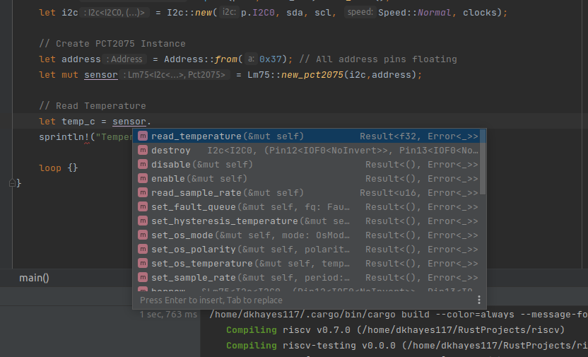
The impl block above uses the specific type <ic::Pct2075>, therefore the contained functions can only be applied to an I2C instance created for a PCT2075 sensor. This is where our functions for the sample rate control will be contained since the lm75 does not have this functionality.
The final piece of the puzzle is the extra addressing modes. Sensors that support only 8 addresses can easily determined with three booleans and some bit shifting and logical ORs. The introduction of the extra 19 addresses proves to be all over the place and not directly calculable, therefore a custom address is used to directly assign the sensor's address.
/// Compute device address from address bits where bits are not floating
impl From<(bool, bool, bool)> for Address {
fn from(a: (bool, bool, bool)) -> Self {
Address(DEVICE_BASE_ADDRESS | ((a.0 as u8) << 2) | ((a.1 as u8) << 1) | a.2 as u8)
}
}
/// Support custom (integer) addresses
impl From<u8> for Address {
fn from(a: u8) -> Self {
Address(a)
}
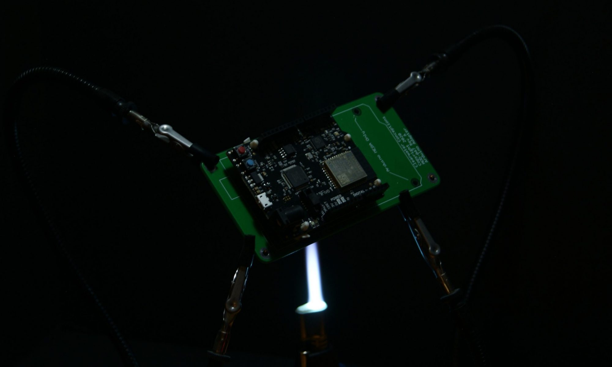
}With all our new functionality implemented, we can put it to the test in hardware. The program below is written for the HiFive1 Rev B microcontroller. Success! The serial console printed out 26.250°C which proves that we have recieved the full 11-bit resolution. A pull request has been created for the LM75-rs crate. Once merged, anyone can easily implement a PCT2075 temperature sensor in Rust!
#![no_std]
#![no_main]
extern crate panic_halt;
use hifive1::hal::i2c::{I2c, Speed};
use hifive1::hal::prelude::*;
use hifive1::hal::DeviceResources;
use hifive1::{pin, sprintln};
use riscv_rt::entry;
use lm75::{Lm75, Address};
#[entry]
fn main() -> ! {
let dr = DeviceResources::take().unwrap();
let p = dr.peripherals;
let pins = dr.pins;
// Configure clocks
let clocks = hifive1::clock::configure(p.PRCI, p.AONCLK, 100.mhz().into());
// Configure UART for stdout
hifive1::stdout::configure(
p.UART0,
pin!(pins, uart0_tx),
pin!(pins, uart0_rx),
115_200.bps(),
clocks,
);
// Configure I2C
let sda = pin!(pins, i2c0_sda).into_iof0();
let scl = pin!(pins, i2c0_scl).into_iof0();
let i2c = I2c::new(p.I2C0, sda, scl, Speed::Normal, clocks);
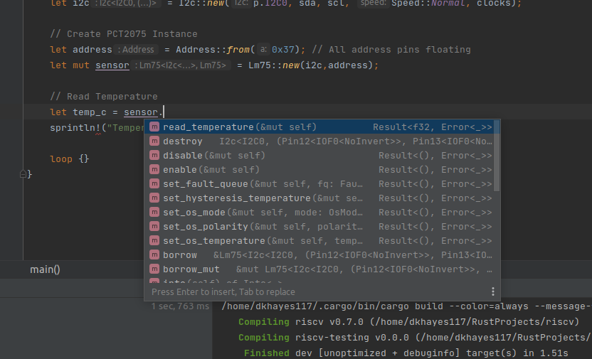
// Create PCT2075 Instance
let address = Address::from(0x37);
let mut sensor = Lm75::new(i2c,address);
// Read Temperature
let temp_c =
sprintln!("Temperature: {}ºC", temp_c);
loop {}
}-Your friendly, neighborhood engineer