I have been reviewing a couple of pull requests to add ADC support for the riscv-rust /gd32vf103xx-hal . Since the Longan Nano dev board comes with an 160x80 RGB IPS LCD screen, I decided to use Embedded Graphics to debug the conversion 🙂
The following code was written as another example for the riscv-rust /longan-nano crate. The program starts with initialization by taking ownership of the device peripherals which is a singleton to ensure singlular ownership. The clocks are configured through the RCU, an internal peripheral that is analogous to the RCC for the STM32.
#[entry]
fn main() -> ! {
    let dp = pac::Peripherals::take().unwrap();

    // Configure clocks
    let mut rcu = dp
        .RCU
        .configure()
        .ext_hf_clock(8.mhz())
        .sysclk(108.mhz())
        .freeze();

    let mut afio = dp.AFIO.constrain(&mut rcu);
The LCD screen pins are configured setting them up correctly for SPI communication. I'm not going to dive into this configuration, but for more information you can find it here.
    let gpioa = dp.GPIOA.split(&mut rcu);
    let gpiob = dp.GPIOB.split(&mut rcu);

    let lcd_pins = lcd_pins!(gpioa, gpiob);
    let mut lcd = lcd::configure(dp.SPI0, lcd_pins, &mut afio, &mut rcu);
    let (width, height) = (lcd.size().width as i32, lcd.size().height as i32);
Now for some Embedded Graphics! First thing is to set the background black by drawing using a rectangle constructor. The upper left corner is defined as well as the screen width and height, and filled with the color we defined Rgb565::BLACK. The draw method takes a mutable reference of the lcd and paints the rectangle essentially clearing the screen.
    // Clear screen
    Rectangle::new(Point::new(0, 0), Size::new(width as u32, height as u32))
        .into_styled(PrimitiveStyle::with_fill(Rgb565::BLACK))
        .draw(&mut lcd)
        .unwrap();
The text style that we want to write our ADC values in is constructed defining font, foreground, and background colors.
// Text style configuration
let style = MonoTextStyleBuilder::new()
.font(&FONT_9X15)
.text_color(Rgb565::BLUE)
.background_color(Rgb565::BLACK)
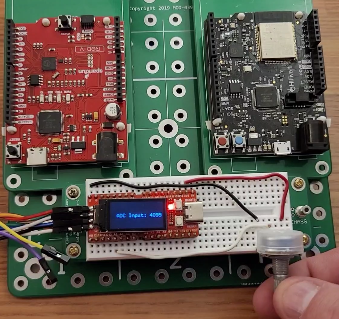
.build();The ADC reads an analog value, in this example a voltage supplied from a 5k potentiometer, and converts it to a digital value. The GD32V103F's ADC has 12-bit resolution, which will map the analog value to a value between 0 and 4095 ( 2^12 - 1). The pot allows us to change the voltage level seen by the analog pin (PA0). The two outside pins of the pot are connected to ground and 3.3v with the middle pin connected to pin PA0. Even though we used GPIO A for the LCD, pin PA0 is not used so we can utilize it for our analog reads. ADC0 is configured with a clock signal and pin PA0 is configured as an analog input. Something worth mentioning is that with Rust, every pin has its own type making it impossible to assign a digital pin as an analog input or vice versa.
    // Setup ADC
    let mut adc0 = adc::Adc::adc0(dp.ADC0, &mut rcu);
    // Configure pc0 as an analog input
    let mut ch0 = gpioa.pa0.into_analog();
In order to write our read ADC value to the LCD, we need it as a string slice (&str). With std environments we could use the format! macro, however we are in a no_std environment without an allocator. The heapless crate allows us to define a fixed length buffer on the stack instead of needing an allocator to create dynamic memory on the heap. With our buffer defined to hold our &str value, we also need to add a delay.
RISC-V has a control and status register (CSR) mcycle that counts CPU cycles and can be read for delay purposes.
    //create static buffer for formatting data
    let mut buf: String<16> = String::new();

    let mut delay = McycleDelay::new(&rcu.clocks);
The last part of the program is an infinite loop block that reads the PA0 pin, converts the value to a &str buffer and prints it to the LCD using the embedded graphics we setup earlier. A 250 ms delay is added for some settling time.
    loop {
        buf.clear();
        // read the analog value on pin convert for printing to LCD
        let data: u16 = adc0.read(&mut ch0).unwrap();

        // format ADC data
        write!(&mut buf, "ADC Input: {}", data).expect("Formatting Failed");

        // Create a text at position (15, 40) and draw it using style defined above
        Text::new(&buf, Point::new(15, 40), style)
            .draw(&mut lcd)
            .unwrap();

        delay.delay_ms(250);
    }
We now have a working program to visually debug our ADC implementation! It may seem like a small thing, but it is so rewarding to see the value on the LCD as the value changes.
-Your friendly, neighborhood engineer